Note: Factory front site must removed for installation. See front sight removal instructions below for more detail. One side of forend must remain rail free for full folding of gun.
Installation Instructions For #R8Tools required: 5/32 allen wrench, 3/32 allen wrench, T15 torx wrench, and a flathead screwdriver (torque wrench recommended)
1. Make sure magazine is removed and chamber is empty.
2. If not already done the front sight must be removed for install.

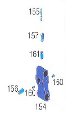
-Remove 2 set screws (diag #160) located on the sides of the front sight body(diag #154) with a 3/32” allen wrench.
-Use factory tool that came with SUB9 rifle or a thin nosed set of needle nose pliers(like we did) to remove the front sight post (diag #155) thru hole in top of front sight body.
-Remove the windage barrel (diag # 156) from front sight body with rod smaller than the windage barrel such as a punch or the back of a pen. Should slide out the side of the front sight body with a little pressure.
-Screw front sight post a few threads back into the plastic insert (diag #157) that is now exposed from top and use the front sight post to pull out the plastic insert.
-With a 5/32” allen wrench back off or remove the set screw (diag #161) that is now exposed from the top of the front sight body.
-The front sight body may or may not require some heat to break the adhesive that helps to hold it in place. Heat gun is recommended if it does require heat since an open flame may discolor barrel if touched directly. Front sight body should slide off the end of the barrel.
3.Remove stock forend.
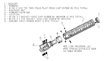
4.Configure R8 forend (part #2 in exploded view diagram) with rails at whatever location you desire. Forend does not have any predetermined top or bottom as all sides are indentical. To attach rails place grommet into locating hole from the inside of the forend (hold in place with finger or popsicle stick or alike if your finger can't reach). Place rail into position. Place 10-24 x 1/2" flathead screw through the rail and into the grommet and tighten till grommet is slightly flexed and somewhat conformed to the forend ID radius.
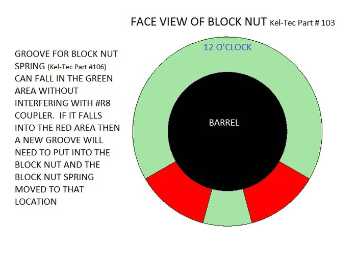
5. Place coupler (part# 6 in exploded view diagram) over barrel and back till it stops and ears are over part of the barrel block. Make sure prior to this that the block nut of the gun is screwed down to the desired position as this controls how tight the gun locks into the firing position when the trigger guard is shut. The wire spring around the the block nut that extends thru the lip groove and rests in the serrations prevents the lock nut from loosening. If this springs falls around the 5 o'clock or 7 o'clock position it may interfere with the coupler clearances. See picture below. Either cut new groove in lip or turn the coupler upside down so that clearances are achieved.

6. Place part #'s 7, 8, &9 in place as shown in diagram if they were previously removed (these are shipped in place). Tighten only #7 cap screws into the corresponding #9 nuts until coupler just turns on barrel with minimal clearance.
7. Place parts #8 and #9 into place according to the diagram if not already done so. IMPORTANT:Before tightening make sure the gun is unfolded and locked into its firing position, this orients the square back plate of gun that the coupler orients off of. After making sure coupler is slid as far back toward the receiver as it will go and that it is atleast part of the way over the square plate, then tighten #8 cap screw into corresponding #9 nut until the coupler ears contact (6ft/lbs MAX, DO NOT OVERTIGHTEN, this doesn’t hold anything on, it just orients the forend to the square plate) the square back plate of the gun that contacts the polymer reciever.
8.Tighten #7 cap screws into #9 nuts. This clamps the barrel and prevents movement forward and back (while also locking the barrel relationship to the square plate). If using a torque wrench, tighten to 9 ft/lbs. If you don't have a torque wrench tighten down until you can't move the coupler by hand radially or linearly and then tighten the bolts a good 1/8th turn further (checking this is explained next). When shooting for the first time, check to see if forend is creeping forward every 1 or 2 shots for atleast the first ten shots (try to have a good purchase on the forend when shooting for this check to make sure its getting a good jolt). If a gap should appear then the forend is moving forward and #7 cap screws need tightened into #9 nuts more, use of witness marks on the #7 cap screw heads help determine further tightness should you need to loosen the bolts to pull the forend back against the gun's lock nut. This gap check is mostly helpful in allowing those without a torque wrench determine whether they have #7+#9 hardware tightened properly but should also be done for those using torque wrenches as a double check.
9.Now part #s 5, 4, 2 , and 1 must be assembled into one unit. Place #4 (threaded ID end first) over the nose of part #5. Then place part #2 over the nose of part #5 (see diagram).Place part #3 screw (6-32x3/8 torx plus flathead) into the countersunk holes in part #2 and screw into the threaded holes in the OD of the nose of part #5. Just snug till all 8 are in place, then tighten. Try to snug and then tighten opposing screws, like you would tighten lug nuts on a tire. Now place the endcap (part #1) in the front of the forend (part#2) and use 2 more part #3 screws to secure. Use of Blue Loctite 242 Threadlocker (medium strength) or other manufacturer equivalent is recommended for the #3 screws (6-32x3/8 torx plus flathead) , a little bit goes a long way so place just a little drop on a spot on the front of the screw thread and it will spread around when screwed in. Blue Loctite 242 Threadlocker will take a set in 10 minutes and should fully cure in 24hrs and be ready for use.
10.Place part # 5, 4, 2, and 1 unit over the barrel (part # 5 first). Point muzzle upward. Slide back till you are able to thread part # 4 (knurled nut) onto the coupler (part #6) that was installed previously. Thread until coupler (part# 6) is able to contact forend adapter (part# 5) and then orient so that the mating tangs engage, then finish tightening part # 4 down to lock into place.
To index the forend: Unscrew knurled nut till forend can be lifted up (approx 1/8" movement needed) and spun into next location (90 degree increments), let the forend back down for tangs to engage, tighten knurled nut to lock in place. If knurled nut seems gritty when tightening and loosening, apply a small amount of light oil to threads.